Kinect pose calibration
The Kinect RGBD sensor on ARIPS is mounted on a moveble joint can can be tilted up and down with a SCS215 servo. Due to inaccuracies of several mechanical parts, the exact tilt angle of the Kinect can be perceived only up to a certain precision. Also the xyz position offset is not completely fixed, since the mounting rods can start to oscillate during acceleration and breaking of the robot when driving around.
This pose inaccuracy was no bigger problem when the Kinect was used solely for navigation purposes, since the usual SLAM algorithms could deal with the small noise. However, the exact physical pose of the Kinect w.r.t. the robot base is required when it comes to grasping detected objects by the ARIPS Arm. Even tiny inaccuracies of only a few mm or fractions of degree can lead to wrongly perceived position of the object, and the gripper end effector will not reach the object correctly.
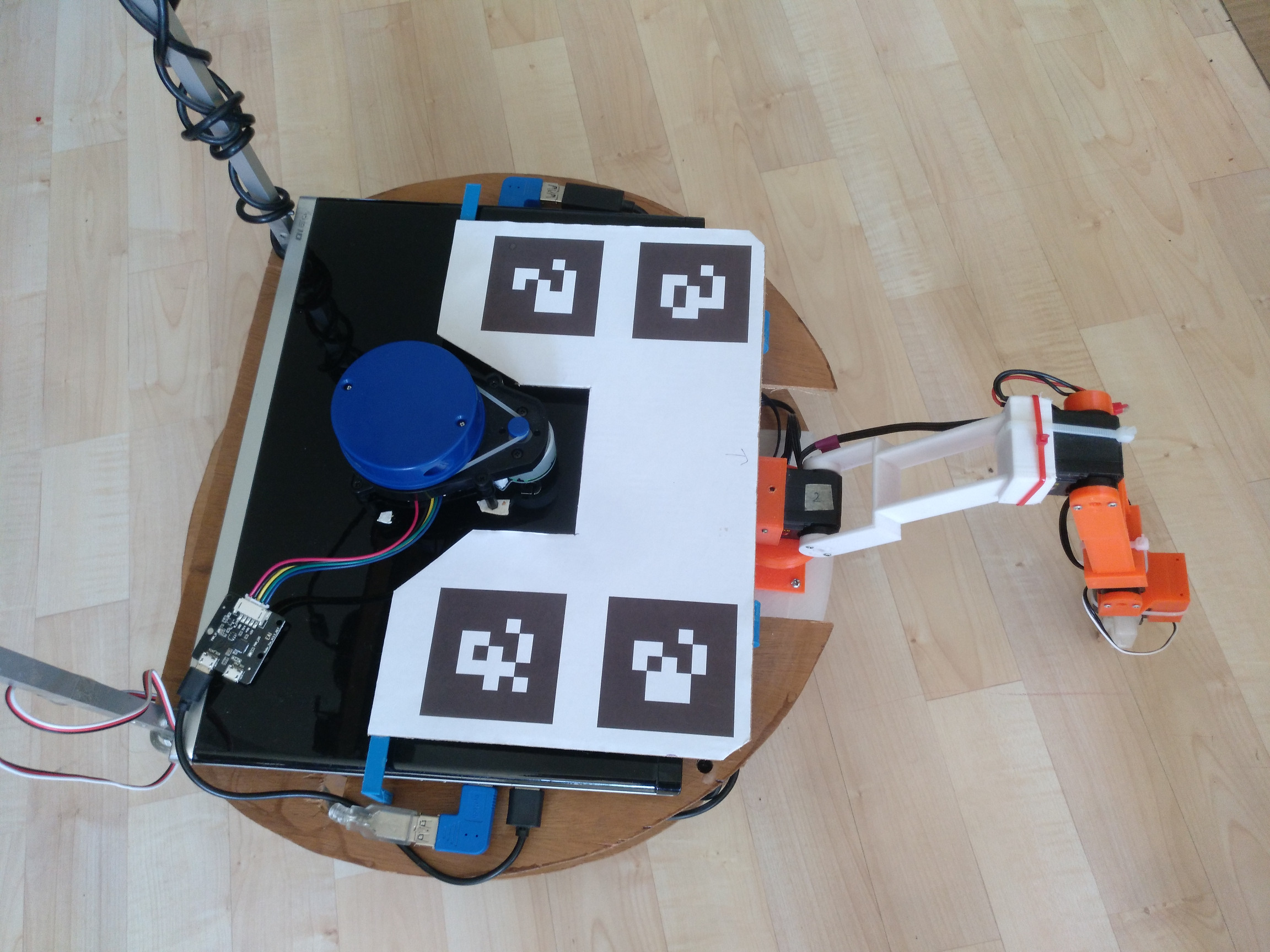
Robot marker plate
To have a more precise estimation of the current Kinect pose, a calibration plate with 4 AR markers is placed on top of the robot. The markers are tracked via the ar_track_alvar ROS package, which also uses the Kinect’s depth data to estimate the marker’s full 3D position and orientation. Theoretically only one marker could be used, but the pose estimation is way more precise when using multiple markers apart from each other by several cm.
 |
 |
|---|---|
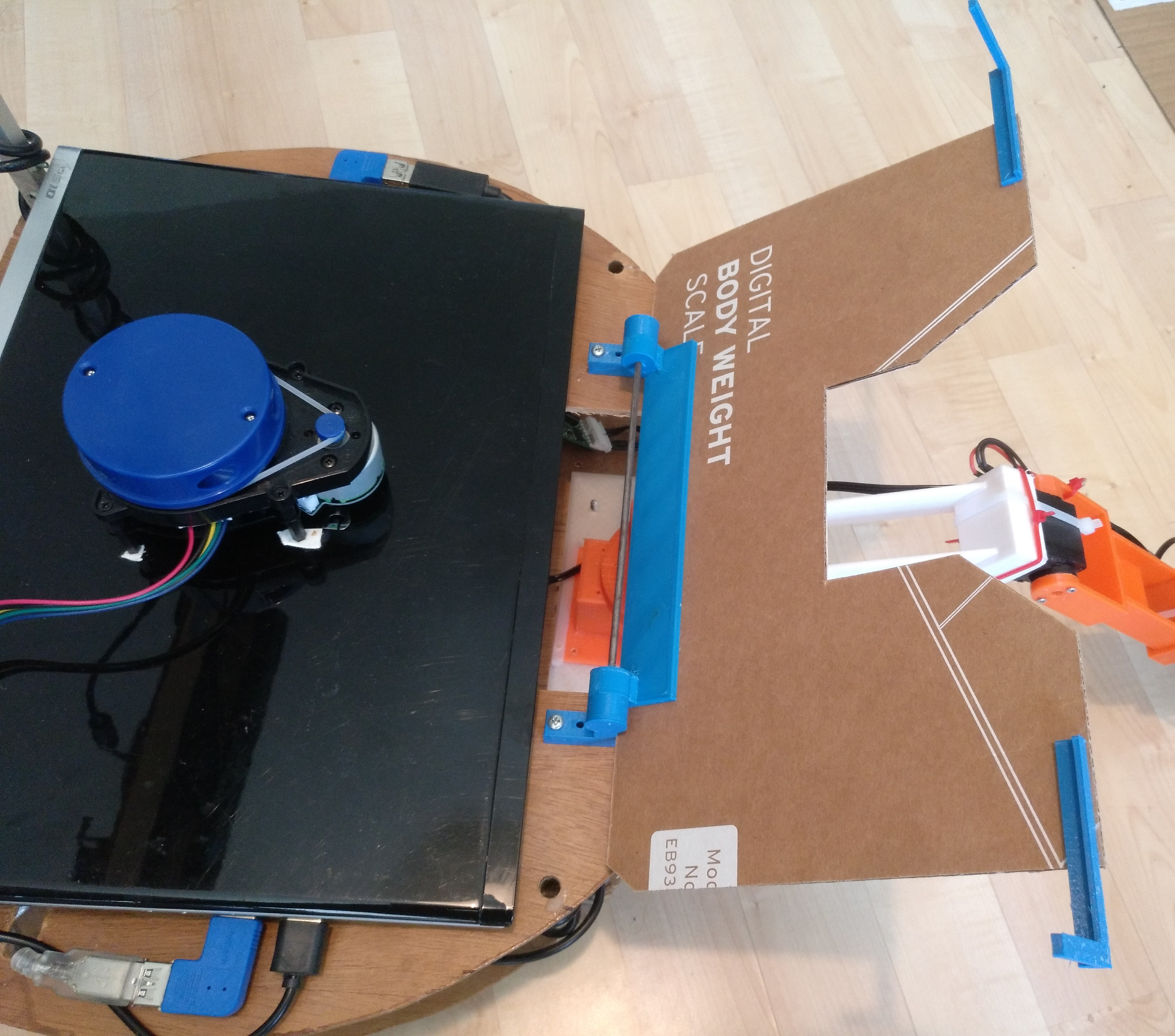
| Marker calibration plate on robot | Plate opened to access onboard laptop |
The marker plate consists of a spare cardboard cutout, mounted on some 3D-printed parts allowing to flip up the plate for easy access to the onboard laptop.
Ground marker plate
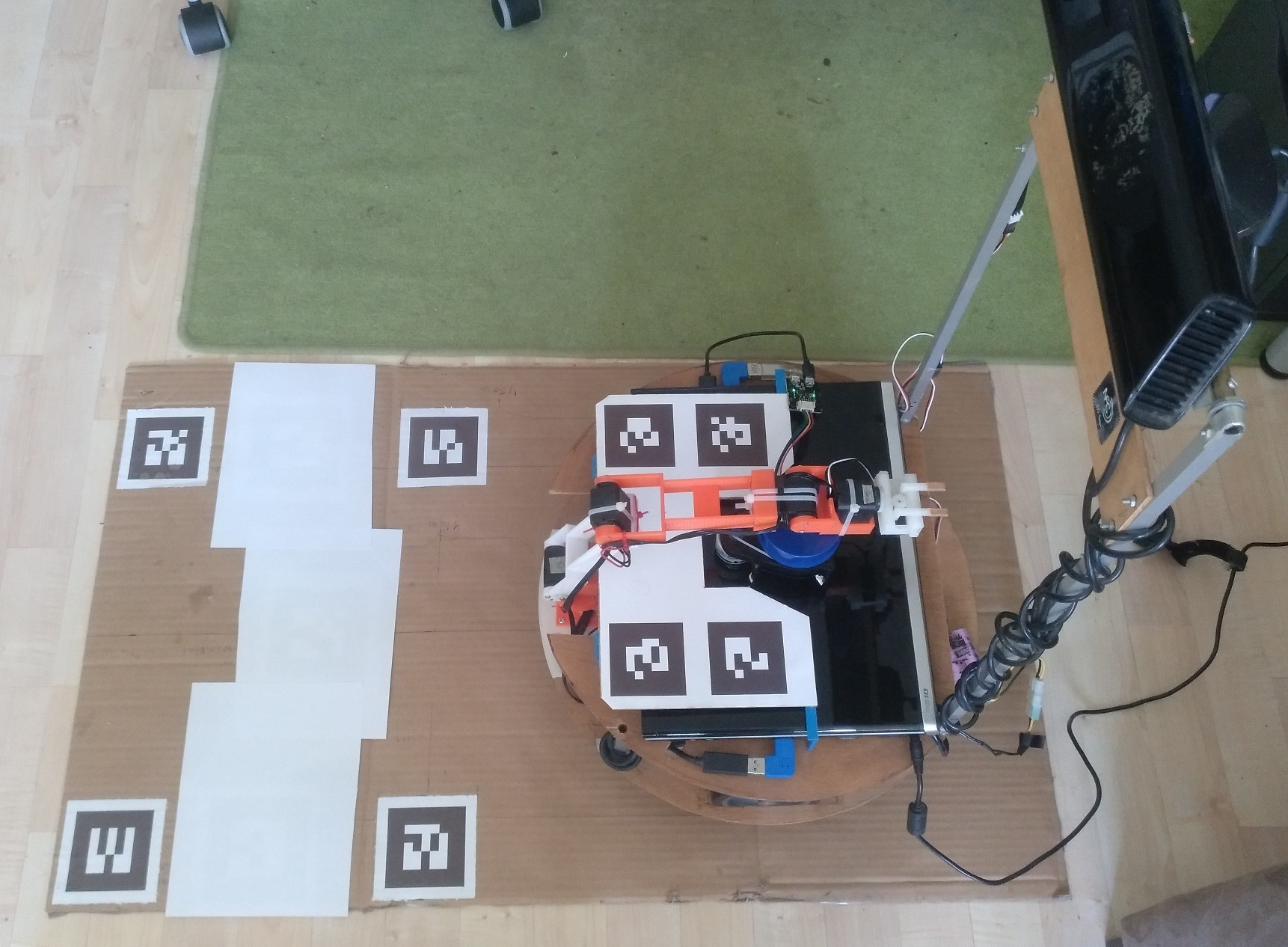
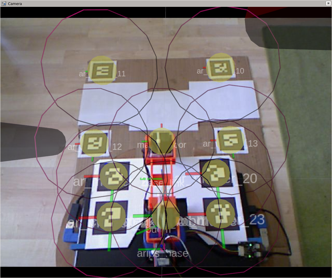
Since the mounting pose of the marker plate itself is prone to construction error, we cannot just take the construction pose, but instead need to manually calibrate its pose w.r.t. the robot base center. This is done in turn with a ground calibration plate. The ground calibration plate consists of 4 further AR markers and some additional lines to indicate where to place the robot for calibration. On the flat ground plane, all distances between the robot base center and the markers can be measured quite precisely and thus can be considered as known.
 |
|---|
| Robot placement on ground plate for robot marker plate calibration |
 |
 |
|---|---|
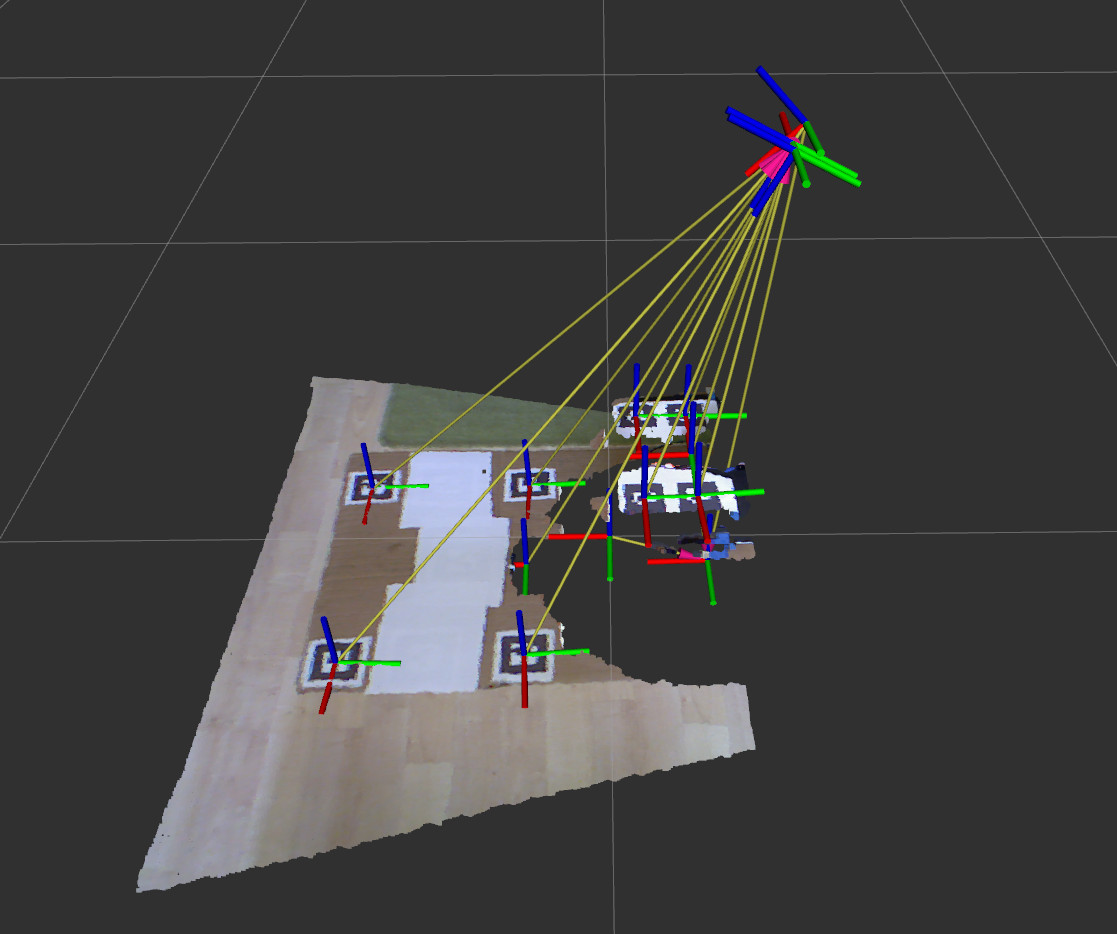
| Marker transformations in RVIZ | Kinect view |
Calibration of the robot marker plate pose
To calibrate the robot marker plate position, the robot is placed on the ground calibration plate, and the Kinect is tilted down to capture all 8 markers of both the robot and the ground calibration plate (see above). Using the manually measured coordinate information of the groundplane markers arips_baseTground_marker and the transformations ground_markerTkinect_base, robot_markerTkinect_base as seen by the Kinect, we can estimate the transformation arips_baseTrobot_marker. This transformation is stored in a configuration file and is not altered during runtime later on.
Kinect pose estimation
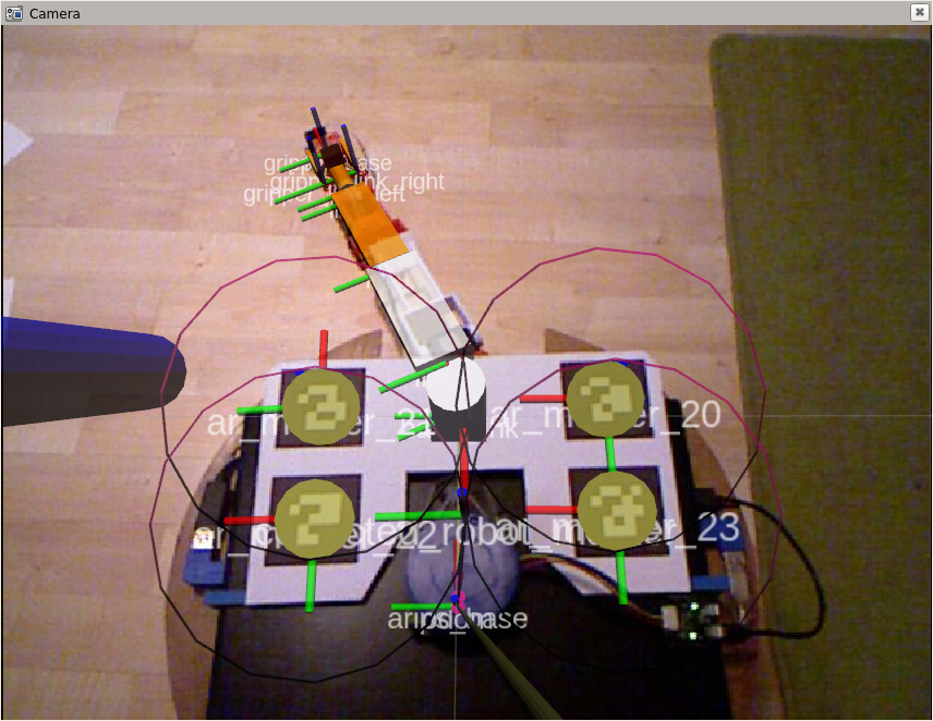
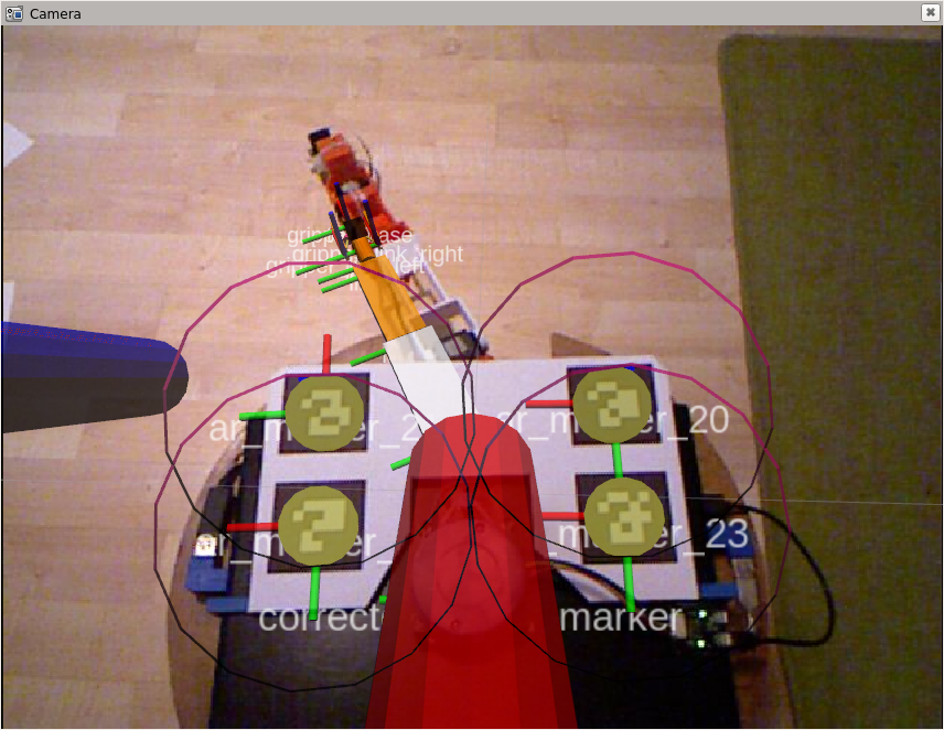
Once we know arips_baseTrobot_marker, we can re-compute arips_baseTkinect_base (i.e. the Kinect’s pose wrt. the robot base) during runtime whenever the Kinect sees the robot calibration plate. Note that the robot markers might not be visible if the Kinect is pointing straight forward. In this case the coarse estimation from the tilt servo’s angular feedback is used to estimate the Kinect’s pose. However, when grasping an object, the Kinect is tilted down anyway, and the markers become are clearly visible.
 |
 |
|---|---|
| Calibration on: the reconstructed arm pose matches the visual position in the Kinect’s view. | Calibration off: the reconstructed arm position is way off the visual pose in Kinect’s view. |